Triple
Global wind capacity needs to triple by 2030 to meet net-zero pathways.
IEA, GWEC
Eliminate the largest crane on every wind project, onshore and offshore.
Taller turbines and heavier components, installed and serviced without heavy-lift cranes or vessels. Conventional cranes and installation vessels are hurting the economics at today's installation and maintenance scale, and are being challenged by new heights and weights.
Sample fixed-foundation offshore project · 15 MW reference, 67 units · based on real project values
Reference turbine
15 MW
Installation campaign vs WTIV
$152M lower
Validated by
Arup · Kent Engineering · ABS
Cost figures are modeled from real project values. Arup, Kent Engineering, and ABS reviewed the load modeling and structural design, not the cost model.
The same KINKA LIFT™ platform that installs new turbines services the existing onshore fleet, at any hub height and without heavy-lift cranes.
Blades, gearboxes, generators, and transformers replaced in service, at hub heights conventional cranes struggle to reach.
Learn moreLarger, more productive components fitted to existing foundations, extending asset life.
Learn moreControlled teardown at end of life, on the same platform, without heavy-lift cranes.
Learn moreTriple
Global wind capacity needs to triple by 2030 to meet net-zero pathways.
IEA, GWEC
425 GW
EU REPowerEU and UK Net Zero offshore + onshore wind targets by 2030.
European Commission, UK BEIS
20-year fleet
A growing share of installed turbines is reaching end-of-design-life this decade.
GWEC, BloombergNEF
Onshore towers keep getting taller and components heavier, on sites that are harder to reach. Offshore nacelles are approaching 1,000 tons. Conventional cranes scale exponentially with both height and component weight. Only five vessels in the world can install and service a 15 MW turbine, and they're booked on new builds.
The result is delayed deployments, higher levelized costs, and a major component replacement backlog that grows daily as the global fleet ages.
CLS Wind addresses the lift itself, with a platform that scales linearly with height and reuses the lower-cost cranes, vessels, and local crews operators already have. It is built on more than 70 years of proven offshore oil and gas jack-up platform engineering. Two products, one platform principle: KINKA LIFT for onshore work, ORCA LIFT™ for fixed and floating offshore.
FIG. 01 · Crane needed vs hub height
Crawler crane, or a 250 t class road-mobile crane.
Smallest class whose published load chart covers the lift. Site practice often goes a class higher for rigging, lift radius, and wind margin.
The taller the hub, the bigger the crawler crane. With CLS Wind the crane lift stops near the ground and the platform carries the component the rest of the way.
Crane lift
140 m → 10 m
Conventional
5 vessels
worldwide can lift more than 1,000 t to a hook height above 150 m, which is what a 15 MW turbine needs. They are booked on new builds.
With CLS Wind
Low lift
The vessel lifts the component only 20 to 30 m, to the platform at the base of the tower, and the platform carries it to the nacelle. That opens the job to smaller, widely available vessels.
Today's gearbox swap is 12 to 15 t at 88 m. A 15 MW direct-drive nacelle is about 1,000 t at about 150 m. The platform is sized to the load, so the approach is the same either way.
Where the load goes
Conventional crane
Tower-mounted crane or climber
CLS Wind
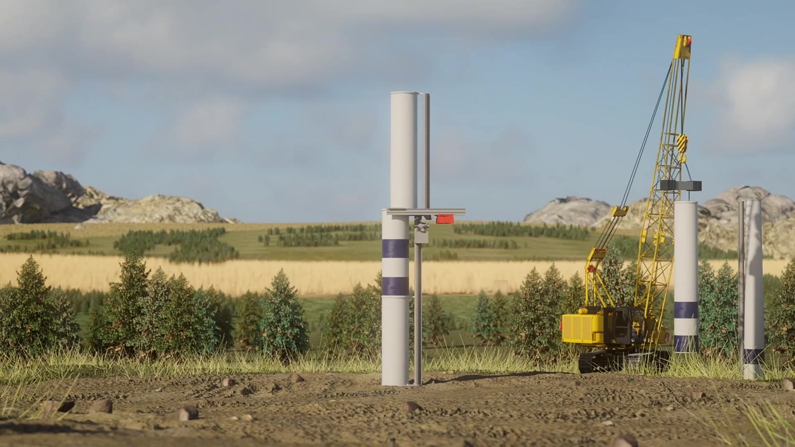

An elevating platform that lifts and replaces wind turbine components at hub heights conventional cranes struggle to reach. Sensor-informed, operator-directed.
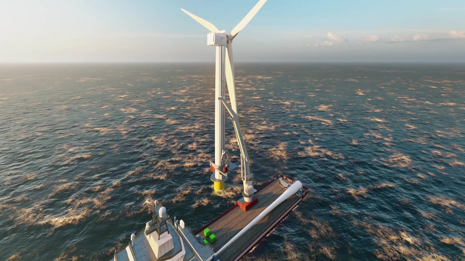

Elevating and installation systems for offshore wind, with variants for fixed-foundation and floating platforms. ABS Approval in Principle for the 15 MW offshore concept.
Whether onshore, fixed offshore, or floating offshore, the vertical loads go into the foundation rather than the tower. They route through CLS Wind structural chords into the foundation, monopile, or floater, which is why existing turbines, new turbines and retrofit candidates are all compatible.
§ 01
Vertical lift loads route through structural chords into the foundation, monopile, or floater, rather than the tower.
§ 02
The existing tower is largely bypassed as a load path. The tower design is unchanged.
§ 03
The same platform installs new turbines and services existing fleets. Validation transfers across comparable geometries.
Validator · 01
Third-party load modeling. 15 MW fixed offshore.
Validator · 02
Independent load modeling. 15 MW floating, three-column semi-submersible.
Validator · 03
Approval in Principle. 15 MW offshore concept.
Across the United States, the United Kingdom, and Europe.